
This is a photo documentation of my first build of Greenboy's amazing fEARful bass speaker design.
For those of you who don't (yet) know, it's a nicely designed 3-way bass speaker cabinet with a 15", a 6", and a tweeter/horn, with passive crossovers to manage the distribution of frequencies to the 3 drivers.
I'm writing this in advance of the build or ever playing through one of these, so bear in mind that all these comments are from what I have read and learned about the fEARfuls.
I'll add some comments after I'm done and then you can judge how well my expectations were fulfilled.
The cabinet volume, bracing and materials are matched to the drivers to produce a remarkable amount of clean volume at a very wide range of frequencies.
Also, due to the crossovers and the alignment of the drivers the off-axis response is very good, so the resulting output should sound roughly the same everywhere in the room.
To top it off, the weight is pretty good too. The resulting build should come out to somewhere around 50 pounds.
For comparison, my best 410 cabinet, a Gez Benz Uber 410, weighs 72 pounds and is not considered too heavy.
The efficiency of this 8 ohm cabinet won't be as high as a typical high-quality 410, but given enough power it should get louder, cleaner, and lower than any commercial 410 is capable of.
My cheapo workshop is being built as I proceed with this project.
It is our two-car garage which we don't use for the cars, but we do use for storage, bikes, a fridge and the air hockey table.
I hung up three fluorescent light fixtures.
My workbench is a couple of adjustable saw horses with 2x4s on top and a solid core door on top of those.
Feels pretty luxurious to me!
This project took me quite a while to complete.
Part of that is my being a chicken and proceeding slowly and carefully.
Part is that I just didn't have a lot of tools, and sometimes I needed a tool or a part before I could continue, and I had to wait until I was able to get it.
Part is that I sometimes only got a few minutes between coming home from work and being with my family.
So in the construction section I've counted any day on which I put in any time, even if it was only 15 minutes.
OK, I admit it. Not only do I not own a table saw, I'm a chicken and not historically the most handy of guys. It feels a bit like cheating, but for me it's still an intimidating prospect. So I ordered a "cut kit" from Leland Crooks at speakerhardware.com. The wood came pre-cut out of voidless 1/2" baltic birch plywood. I also got the crossovers pre-built. Next time I would probably order parts and build the crossovers myself. Cutting the wood is a bit scary, but depending on my shop skills and confidence at the time I may do that also.


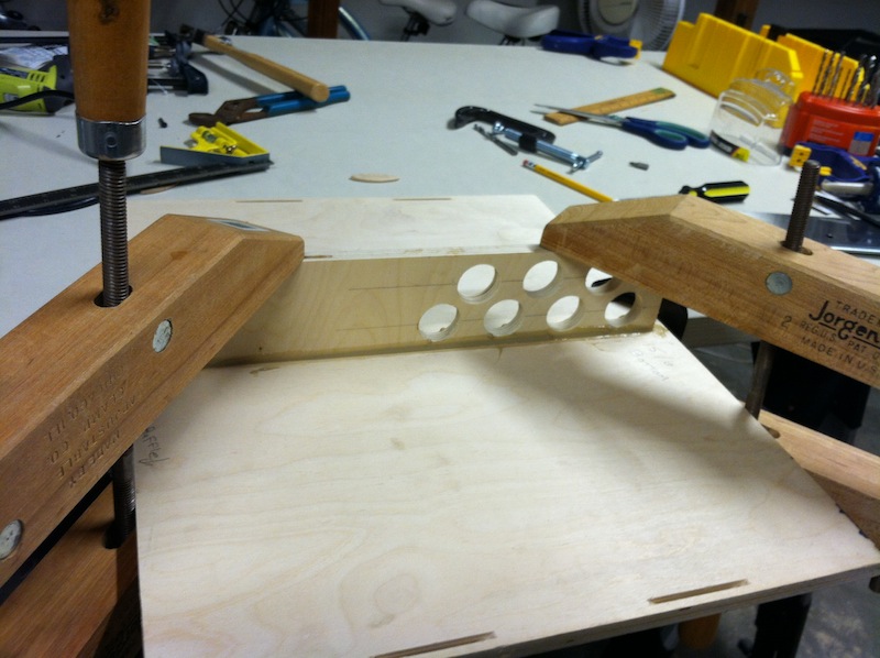
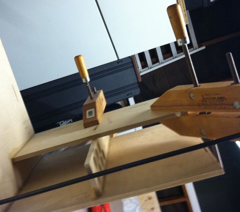
Construction was done using PL Premimum glue, clamping and sometimes screwing the joints together to hold them in place while the glue cures.
The curing process takes up to around 24 hours.
Theoretically, you can probably put almost all of this together in an hour and a day later all the wood assembly is done.
For the most part, I glued/clamped/screwed one major joint at a time, and let it cure for a day before moving on to the next part.
This is largely due to the fact that I don't have enough clamps.
So I'm going to have to get a few more, like some big pipe clamps.
Clamps, if you didn't know it, are essential to something like this, so that you can hold the wood together and square while the glue cures.
A nice square box with no air leaks is really important to a good speaker enclosure.
I'm trying to get as close as I can, but frustratingly I can see my errors immediately after it's too late to correct them.
I made some type of error at almost every step along the way, and I'll try to detail them as that may be instructive to some.
Some folks might complete this build in a couple of days.
It will be more like two solid weeks for me, as I'm building my workshop as I go, plus I only get a little time each day to work on it.
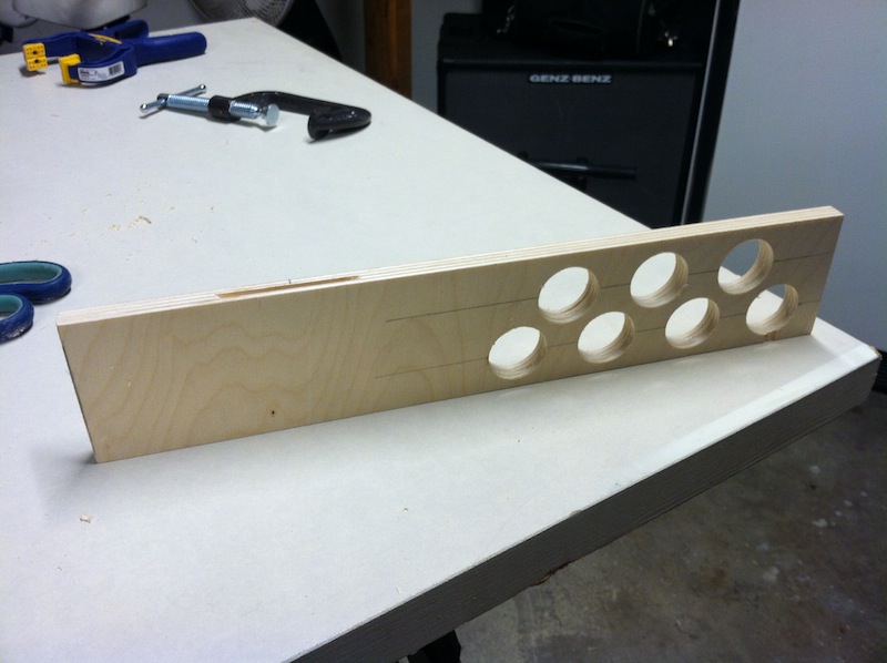


Because I am an idiot, I didn't try test fitting the drivers into the baffle until now.
So, now I find out that speakerhardware.com made a mistake and cut the hole for the wrong type of high frequency horn.
That means my horn doesn't fit the hole cut out for it.
Great. The baffle is all glued up so it's too late to have them send me a new baffle with the correct cutout.
So, I need to cut the new hole, which is a scary prospect for me, but I guess it will be a good introduction to actually making some real cuts.
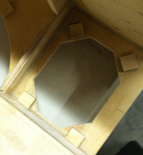
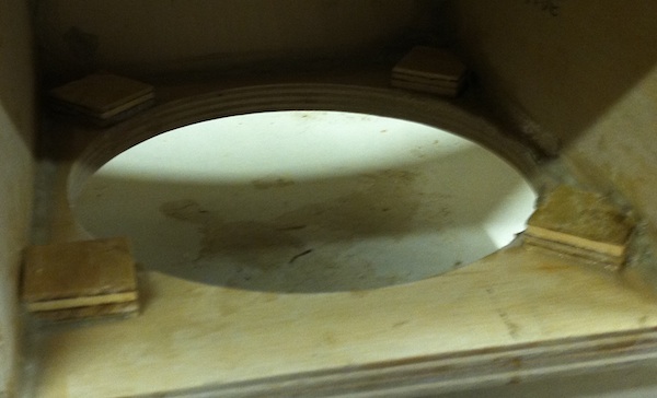
Unfortunately, the old and new holes intersect so I need to fill in some of the old hole before cutting the new one.


The fix seemed to work pretty well. I am learning a lot from this project!
I drilled holes at the corners and in the middle, and roughed it out with a coping saw.
When it could fit, I used the Japanese pull saw to get nicer cuts.
I was going to use the jigsaw, but it seemed hard to fit in there and I ended up just hand cutting the whole thing.
A bit of sanding and it doesn't look so bad.
In any case, it doesn't have to look pretty, as long as it works to support the drivers and create a good airtight seal.


New year's eve... Thought about colors a bit. I think I'll go with tinted DuraTex, maybe Turqoise for the body and white Krylon paint for the baffle.


Back at work now, so I just get to work on this project a few minutes every couple of days.
Also, waiting on some extra screws and doodads from speakerhardware.
I decided to go with orange DuraTex (Sherwin Williams #6884, Obstinate Orange), for the finish. Hopefully that will be here tomorrow.


Greenboy and Duke LeJeune have posted a couple of value changes to the high-pass circuit that should allow the tweeter to reach down further, filling a bit of a gap between the frequencies reproduced by the mid and high drivers.
Fortuitiously, one of the components being replaced is the inductor coil whose orientation I was going to change anyway.
So I'll order the new coil and capacitor and make that change before installing.


Did a bunch of sanding to even up the top edges, so that the top will fit nice and flat and glue up properly.
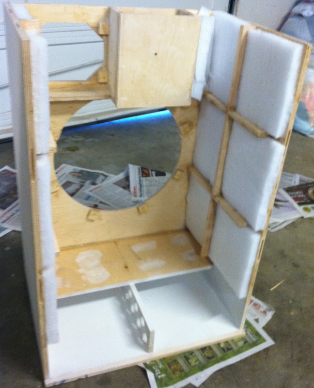
Still need to rip up some of the damping and stuff the inside of the mid chamber, very important so that we don't get nasty phase cancellation as the mids bounce around off the walls of the chamber.
Waiting to get the new crossover parts from speakerhardware.com.
After the crossover is modified, I'll put in the crossovers and drivers and wire them up,
Then I'll glue in the back, wire up the jacks and put in the (optional) top brace and top.
Then I'll do a listening test to make sure it's all working.
Then, I'll do the strap handles and rout the edges so I can fit the corner protectors on.
Then, a final sanding and the DuraTex, the grill and feet.


I realized that I planned badly as far as the strap handles.
I need to drill holes from the outside, and then attach the hurricane nuts to the holes from the inside.
Unfortunately, I already glued in the damping, so it will be a bit of a hassle getting the holes cleanly drilled and attached.
The fabric glue stays tacky for a long time.


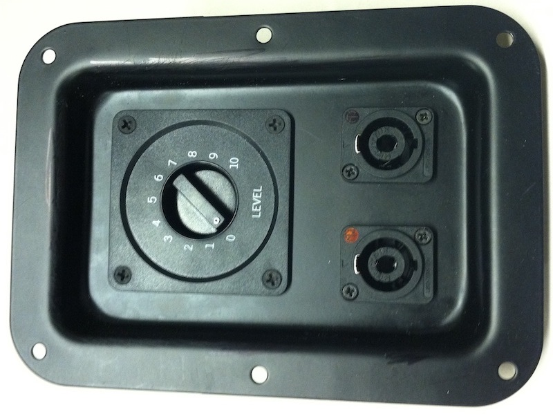
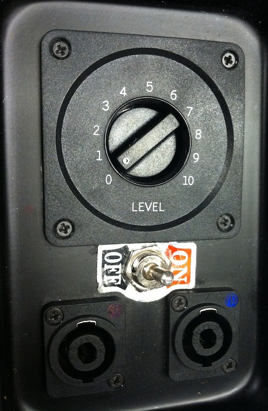
I got the DPDT switch for the mid pad defeat, and the SPST for the tweeter on/off should arrive soon.
I am now thinking that I may leave both of those off for a few reasons.
I don't want to make the wiring too complex since it's my first build.
I would have to rout a new hole and put in another plate.
And, the mid switch is a 3-position (DPDT), and I just found out the middle position would turn off the mid driver, which is a bad thing for the circuit, although I don't know whether the amp, the speakers, or the crossovers could be damaged.
If I don't do that, I can wire up the crossovers, jacks, Lpad and drivers today.
Then I'm just waiting for the one remaining hurricane bolt and I can glue on the back and top.
After that I will round off the edges and sand, apply the DuraTex, attach the grill, corners and feet, and I'm done!

I cut the rubber tubing into 1.125" lengths for grill standoffs, and drilled the holes in the baffle.
I then attached scraps of wood to the inside of the baffle so the grill screw holes would not go all the way through.
The hurricane bolt finally arrived, so I installed that... On to the rest of the cabinet construction.
OK, that was an frustrating but edifying few days.
Although the top is not on, I hooked up the drivers and gave the cabinet a try to make sure all was well, using my Carvin SB5000 and Streamliner amp.
The woofer and midrange drivers sounded good, but no sound was coming out of the tweeter.
With the help of a few very knowledgeable people on the fEARful forum, I traced through the whole circuit.
I used a Digital Multimeter to trace continuity, and a signal generation website to inject sine waves and various types of noise at different parts of the circuit.
I took a signal directly from the headphone output of my PC and connected that to the circuit, so there wasn't lots of scary nasty current running through the circuit or my DMM.
Surprisingly it was quite audible, that tweeter is quite sensitive!
Eventually, I found that one of the terminals on the prebuilt high-pass crossover board was not making good contact with the copper.
I resoldered it to the copper and everything seems to work!
To expand on my debugging, the reason I couldn't find the problem using only a DMM and continuity tests is that the bad connection was not directly connected to the tweeter.
There is a high-pass filter in between them, so there is no simple continuity.
If I had checked on either side of that particular bad solder, I could have found the discontiniuty, but I didn't do that because I was focused on testing problems within each board.

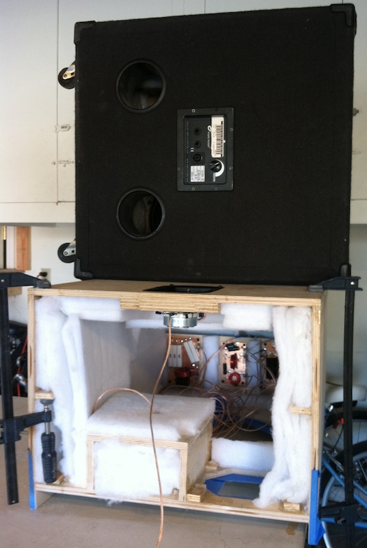
Finally got the courage up to put the top on, so the box is complete and access is now only available through the speaker mounting holes. I added lots of damping, an average of almost 3 layers (3 inches). The internal wiring is mostly held in place by being sandwiched between layers of damping, plus a zip tie to route them where they emerge from the crossover boards.

Did some sanding and planing to get rid of edges that stick out too far.
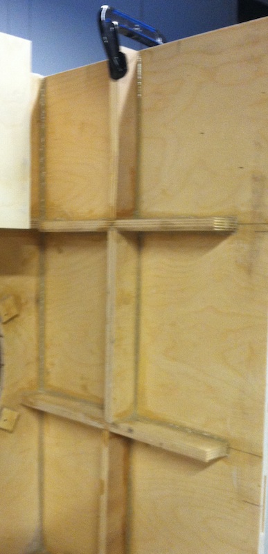
Due to misaligned biscuit holes I've had several pieces be more than 1/4" out of alignment, which has caused me lots of extra effort.
Also I've found several smallish voids in the wood when sanding/planing.
I'm not sure if this is to be expected or not, but I'm trying to fill them as I see them.
I think Leland and company at SpeakerHardware.com are doing a great job, but I have had more than my share of problems with this build.
Maybe that's partially due to my own inexperience, but in addition to the wood problems mentioned here and the miscut tweeter cutout, I've had several problems with missing hardware,
Again, maybe no problem for somebody with build experience, but it poses some difficulty for me.
After the glued up split cures, I should be ready to rout the edges and do a final sanding before applying the DuraTex.


Didn't have much time to work on this for a while... But I got out my router and used it for the very first time. The 1/4 roundoff makes a big difference in the looks of the box, more than I was expecting.

Sanded things off, and rolled on 3+ coats of custom orange DuraTex!

After a few days of drying, it has feet and a grill. It sounds HUGE, clean, and warm. I can't wait to try it out with a band...
